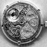
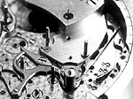
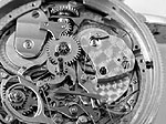
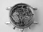
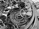
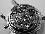
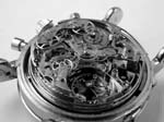
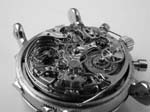
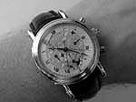
4. Detailed descriptions of the added complications:

With such a bunch of complications to show and discuss, I decided to follow the history of the watch and want to present the complications in their historical order. To that end, we must first discuss briefly the Grande et Petite Sonnerie and Minute Repeater. I won't attempt to discuss its mechanism in detail as such a dissertation would fill many volumes. In addition, the design of the original mechanism is so classical as to have already been discussed in several volumes at least, this example distinguished largely by its diminutive size and exemplary execution. Instead I'll simply offer an overview of what the mechanism does.

The Sonnerie and Repeater:

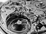
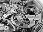
One of the most challenging and certainly the most complex classical Grande Complication, the Grande et Petite Sonnerie and Minute Repeater is an extremely exotic animal. Even today there are only a handful of examples of this grandest of complications and their numbers diminish exponentially as their size decreases. For Philippe Dufour to make a Grande et Petite Sonnerie and Minute Repeater in a wristwatch size in the late 20th century is a major accomplishment, for Louis-Elysée Piguet to do so in a similar size 100 years earlier is nothing short of mind-boggling.
A Sonnerie is a watch that strikes the time in passing, much like a grandfather clock. In "grande strike" position it will strike the number of hours on a single gong at the turn of the hour and, in addition, at the passing of each quarter hour will strike the hours with single chimes and the quarters with double-chimes. In "petite strike" position the hours will be struck on the hour and the quarters only as they pass. For occasions when such music coming from your wrist might not be appropriate, of course it is equipped with a "silent" position as well.

To realize a complete array of passing strike options like this in a clock the size of a small closet and powered by the falling of large weights requires some ingenuity and engineering prowess, but to do so in a mechanism small enough to be worn on the wrist simply boggles the imagination. Sharing all the complexity of a Minute Repeater and then some, it is no wonder that most Grande Sonneries are also Minute Repeaters.

Please click image to listen to the Minute Repeater Sound-file:

The Perpetual Calendar/Thermometer:
The Perpetual Calendar has become a "standard" in the world of complicated watches, but perpetually has its charm as a mechanism that knows a little bit about the future: It "knows" how the date indications will be set in, say, 97 years (needing the adjustment of a single corrector in the year 2100)!
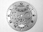
Together with a thermometer, the Perpetual Calendar was added by Franck Muller, at the very beginning of his impressive and successful career. As far as can be judged from pictures, the Perpetual Calendar plate is of excellent execution and of classic design and layout as would seem most appropriate to add to such a traditional movement. The notable exception is the retrograde month indication, forecasting the multitude of retrograde indicators that Franck Muller has become known for in recent years.
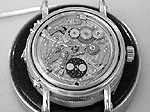
Here are three pictures of the module (with the easily detectable retrograde mechanism at the 12 o'clock position), the Thermometer and of both, the module and the Thermometer, fitted on the dial side, above the minute repeater works. Please note that the retrograde indication mechanism is quite different from a retrograde second as we know them from Paul Gerber or Blancpain, for example:
The Tourbillon:
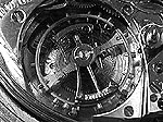
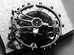
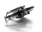
This first item on Paul Gerber's agenda was the construction of the Flying Tourbillon. One cannot believe that this is not only Paul Gerber’s first Tourbillon he ever made, no, it is also the world's smallest Flying Tourbillon. A special challenge here was that the original balance of the Piguet movement should be used in the Tourbillon. Additionally, the Tourbillon cage should mask only the absolute minimum of balance and hairspring. These constraints necessitated the "flying" mounting of the Tourbillon cage. To place the regulator as close as possible to the balance axis, Paul Gerber made a new hairspring with Breguet over coil and Phillips terminal curve (no 57.5 according to the Phillips classification). He also implemented a new escapement with lateral pallet.
That this construction is also more sophisticated, more difficult to assemble and a more visually appealing construction is merely welcome side-effects.
Volker Vyskocil, the owner of the excellent watch information resource www.ClockWatch.de, developed an informative animation of this masterpiece of miniaturization:
To place the Tourbillon in the movement, the cocks for the balance and escape wheel and the bridge for the pallet lever had to be removed and extra space for the Tourbillon cage and its intermediate wheels had to be drilled in the movement’s base plate. It bears repeating that the pressure on Mr. Gerber at this stage, where irreversible alterations are made to the main plate of the movement, was immense. To account for the increased need of power for the Tourbillon, two further modifications had to be applied: A stronger mainspring (which is shorter and has a thicker blade-strength to optimally use the barrel space: 1/3 barrel, 1/3 barrel core, 1/3 free) and two additional jewel bearings had to be inserted with the help of an additionally added Tourbillon bridge on the dial side of the movement that also supports the mainspring barrel. A finicky work, just think of the minute repeater mechanism placed there...

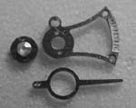
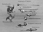
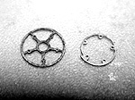
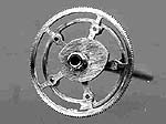
The Tourbillon itself is of classic flying construction. In the first implementation, it was fitted with ruby bearings for the balance axle. Ever the perfectionist, Mr. Gerber decided to change to a diamond cap jewel: A simple modification one might think, but that was not the case. The Tourbillon top bridge and the regulator had to be made a second time completely from scratch to take into account the now increased diameter of the diamond end stone: 1mm instead of 0.7mm of the ruby stone. Consequence: the two screws which fix the cap jewel plate had to move outwards. That means the cap jewel plate, the regulator as well as the entire top balance bridge of the Tourbillon had to be re-done. Here you see the old (top: left and middle) and the new Tourbillon construction (top: right), as well as some parts (low: top balance bridge, Tourbillon bottom plate, Tourbillon cage assembled without balance and hairspring):
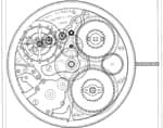
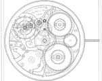
The result in 1995 was again the most complicated wristwatch in the world. As we know now, this was only an intermediate stage, since the owner planned much more. Right now, for most of us, the construction plan looks like a incomprehensible miracle, like a map of a megalopolis:
The Chronograph:
The construction of a new Chronograph mechanism is quite a technical feat that very few manufactures undertake. The broad use of the handful of commonly available Chronograph calibers is ample evidence of this. A Split-Seconds Chronograph is particularly challenging, many times more difficult than a simple Chronograph even, due to the incredible tolerances that must be realized to keep from putting a critical strain on the movement when the Chronograph is engaged and especially when the Split-Seconds mechanism is activated. The fine adjustment necessary and infinitesimal loads that must be balanced against each other make a Rattrapante possibly the most challenging complication to properly set-up and adjust.
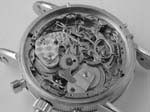
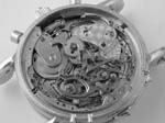
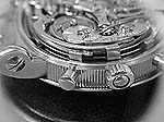
In this special case, the mountain of difficulties was two or three times higher than usual: An incredibly complicated movement, a unique piece, should be upgraded with a Split-Seconds Fly back Chronograph, operated by a column wheel of course. Challenging even more so because the gongs of the Sonnerie and Repeater are in the way of the Chronograph pushers:
The existing beautiful dial should be used which fixes the place for the Chronograph hands. Last but not least the movement should not gain much height which would make the use of the platinum case impossible. Is it any wonder this challenge kept a master watchmaker working for 8 years?

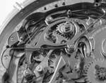
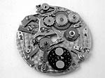
Since the movement was not intended to be fitted with a time-counting mechanism, there was of course no space reserved for it. Forced to use every bit of space that could hold a wheel or a lever, Paul Gerber invented one of the most classic looking and technically demanding Chronograph mechanisms ever seen:
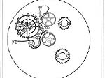
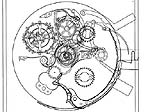
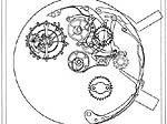
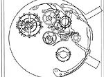
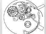
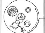
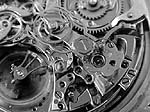
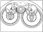
In the end, a classical but uniquely implemented column wheel Chronograph was the result of years of construction, testing, modification, further testing and finally approval. The following plans and videos recorded by Paul Gerber may give you a clearer understanding of the Chronograph works. The construction plans showing the mechanism in the various positions help to understand: (left) Chronograph off, (middle) Chronograph on, (right) Chronograph reset. Please take a look at how the coupling lever connects clock-work and Chronograph mechanism, and how the jumping minute counter is driven:
Video: The Chronograph

Several characteristics of this exemplary Chronograph should be covered more in detail:

The control mechanism:

It is not surprising that Mr. Gerber chose to utilize a column wheel for the Chronograph controls. The column wheel has a lower portion with sixteen ratchet teeth and an upper portion with half as many columns. The ratchet teeth are advanced one tooth at a time by an operating lever and held in place by a jumper. As the column wheel rotates, the ends of the levers for the coupling lever and the brake alternately fall on a space or are lifted by the columns.


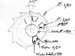
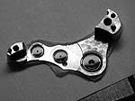
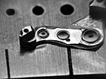
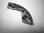
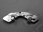
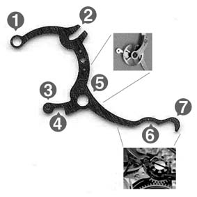
One of the remarkable things about this implementation is the exotic shape required of the coupling lever for it to facilitate multiple functions, the end of the coupling lever became increasingly thin and curvy until its final form was realized (shown here in two different evolutionary stages, new version is on top). In the following I want to describe the fancy details in note form:

  • (1) To fix the coupling lever on movement
  • (2) This slot serves two purposes during the resetting procedure: two pins are operated here: first, it moves the coupling lever out of the power train during resetting (via reset lever), second, it also moves the click of the Chronograph minute wheel (this click ensures proper positioning of the minute wheel)
  • (3) In this hole the operating lever for the jumping minute counter is mounted and coupled in and out of the power train
  • (4) This small indentation helps to control the depth of the allowed movement of the coupling lever. It is adjusted by an eccentric screw mounted on the movement plate
  • (5) Here the jewel for the intermediate wheel is fixed (see small image)
  • (6) Bow, necessary to guide coupling lever around blocking lever (see small image)
  • (7) Pin that interacts with the column wheel through which the lever is operated (see small image)
The jumping minute counter:
As mentioned before, the existing case should be kept. This means that the additional Chronograph should not over egg the pudding too much. One measure to minimize the need for space and fitting points was the use of a jumping minute counter, which by the way counts a full hour (60min) instead of being limited to 30 or 45 min.
Since such a construction utilizes levers to transport the motion of the center seconds counter to the minute counter, Mr. Gerber was more flexible with the placement of the axes. Additionally, less energy is needed.
The Chronograph minute indication is located concentrically to the continuous small seconds at 6 o’clock. That means that the counted time is transported from the drive wheel on the second arbor of the base movement via the intermediate (coupling) wheel to the Chronograph wheel (in the center). From here the impulses for the elapsed minutes are passed on back to the Chronograph minute wheel, via a snail mounted on the arbor of the Chronograph center wheel. This is a more complicated, technically challenging and elegant solution than the common semi-instantaneous minute counter, where a finger on the Chronograph wheel flicks an intermediate minute counter wheel once per minute.
    
The jumping minutes counter principle is similar to a retrograde mechanism of the seconds – to some degree: A lever gauges the snail curve fixed on the Chronograph center wheel. After 59 seconds it falls back to the zero position, thereby using this energy to transport the Chronograph minute wheel one unit forward (read: one minute indication). Such a jumping construction demonstrates a charming perfectionism: technically not necessary, but aesthetically a non-plus-ultra, especially if viewed from the movement side.
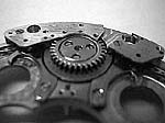
The following pictures, taken in the prototype stage of the Chronograph design, highlight how extremely refined and elegant Mr. Gerber's solution for the Chronograph came out.
A very good illustration of the jumping minute counter is given on a video recorded by Paul Gerber during the construction work of the Chronograph. With most of the parts of the Chronograph yet assembled, it gives you a good and unobstructed view of the jumping counters mechanism.
Video: The Jumping Minute Counter
The Resetting mechanism:
Everybody can imagine that a Chronograph only is really useful if it can be reset to zero. This was not possible with the first pocket watch Chronographs. Finally, when the watchmaker Adolphe Nicolet invented the heart cam in 1884, a Chronograph could be reset to zero after timing an interval without waiting for the Chronograph counters to arrive back on zero.
This is achieved with the use of a reset lever with flat, hammer surfaces pressing against the heart discs that are fixed on the Chronograph counters' arbors (each arbor of the Chronograph - seconds, minutes and hours - needs a heart cam to reset to zero). The reset hammers press against the edge of the heart cams (in whatever orientation they have stopped), causing them to rotate until the hammer is resting against the flat portion of the cam and the counters are reset.
A simple principle – but there is again our old challenge: no space. As you probably guessed by now, Paul Gerber found a way. The heart cams of the Chronograph seconds and minutes counters are not visible in our images (you only can see the heart cam of the split-seconds wheel), but in the next three pictures you can see the horizontally acting reset lever operating a hidden heart cam: (left) Chronograph stopped, (middle) reset lever activated (by screwdriver), (right) reset lever viewed from column wheel:
Very educational are two videos Mr. Gerber made during the assembly. The first shows the reset lever acting on the seconds and minute’s counters and you can also see that it lifts the brake and jumping minute lever out of the way. If the Chronograph was engaged at the time, the reset lever would also lift the Chronograph coupling lever (for proper "fly back" function):
Video: How the Reset Lever works
Video 2 shows the obstacles the base movement presented for the reset mechanism. Notice the way they have been partially buried under the various wheels and brides with a bridge on the rest lever itself being necessary for the seconds hammer to clear the extended arbor of the power reserve mechanism!
Video: The pathway of the Reset Levers
The Split-seconds mechanism:
Never satisfied with "good enough", Lord Arran wanted to have a Rattrapante or Split-seconds Chronograph mechanism installed. Mr. Gerber embraced the challenge as an impassioned watchmaker and as a perfectionist. The result, like the other complications, is a beauty in its own right. As a matter of course, this mechanism also looks like it belonged there from the beginning.
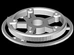
        
Operated by a pusher mounted co-axially in the crown and controlled by an octagonal rim wheel (reminiscent of the famous "MG" logo, don’t you think?), the delicate, pincer-like, split-seconds brake levers gently clamp the split-seconds wheel and stop it. A second push of the split-seconds button moves the rim wheel another step, the brake levers release the split-seconds wheel, and it "catches up" with the Chronograph wheel. The catching up action occurs because of the tiny split-seconds lever, mounted on the split-seconds wheel, which presses against an auxiliary heart cam mounted on the Chronograph wheel arbor. The tension of this lever must be very precisely adjusted so that the split-seconds wheel catches up properly while not placing an undue strain on the mechanism while the Chronograph is running and the split-seconds wheel is stopped.
Video: The Split Seconds mechanism
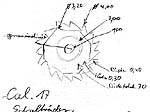
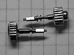
One of the main challenges in the construction of the split-seconds mechanism (in addition to the slender column/rim wheel), was to get the operating lever to connect the pusher in the crown to the rim wheel (around the gongs of course). Paul Gerber also mastered this problem ("of course" one is tempted to say). The following pictures show the newly made winding stem and the almost hidden levers for the Split-seconds operation:
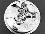
How could Paul Gerber get all these magical works into the movement?
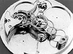
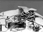
The implementation of the Chronograph mechanism caused some changes to the existing movement. Two changes should be highlighted here. One is a problem of thickness. The additional arbors for the Chronograph wheel and split-seconds wheel of course had to find their way through the central axis of the movement and the jumping minute counter arbor likewise had to find its way through the seconds wheel pinion. Because of this, new, larger pinions were necessary and consequently, new jewels with larger holes.

Mr. Gerber found himself confronted with replacing excellently executed vintage jewels with modern ones, so shaping and polishing a jewel nearly from scratch was the best solution. Here you can see the movement side of the center bridge with old (left image) and new (right image) seconds jewel in place (the far left jewel on the center bridge). Note also the fine finishing on the underside of the bridge.
    
As you can see from both images, the bearing surfaces of the jewels are slightly domed. What is not apparent from the pictures is that the inside of the holes in the jewels are also curved. These "olive" jewels have two major aims: to minimize the friction between pivot and jewel and to assure that the parsimoniously applied drop of oil will be held in place.
The next step was the construction of a new center wheel pinion that could allow the passage of the two new Chronograph arbors (for the Chronograph and split-seconds wheels). This turned out to be one of the most challenging parts to manufacture since incredibly small tolerances had to be handled with utmost precision.
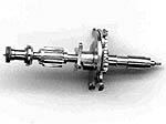
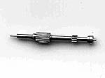
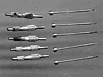
In a "simple" watch, this central axis already bears center wheel, center wheel pinion, the cannon pinion (and minute hand), the hour wheel (and hour hand) and sometimes the seconds pinion (and second hand). In the case of a striking watch, the center axis also has to carry the respective control discs for the striking mechanism. In the end, the final center wheel pinion is a piece of art on its own right. It consists altogether of eight parts: the split-seconds arbor, the Chronograph wheel arbor, the center wheel pinion and the cannon pinion which carries the quarter snail, minute snail and surprise piece, and the four lobed trigger star for the Sonnerie. In the lower part of this picture you can see some of the arbors and pinions that had to be manufactured from scratch.
Put together, this complicated piece looks a bit like something out of an automobile engine:
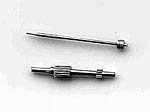
The Chronograph wheel arbor and the split-seconds arbor are exercises in precision machining. Less than 0.3mm had to be drilled out of the Chronograph arbor (for comparison: a human hair is about 0.1mm thick!). The following picture shows the split-seconds arbor (bottom) and the Chronograph wheel arbor (middle) and both arbors put together (top).
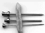
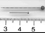
To give an idea how tiny and finicky the split-seconds arbor is it is shown together with a straight pin and a ruler with centimeter scale (the arbor is about 1.4cm long!).
One can imagine how many attempts Paul Gerber had to make to drill a precise hole in the Chronograph arbor. In addition to the center wheel pinion, the pinions for the wheel of the second and minute counter had to be made from scratch. A much easier task, but nevertheless it had to be done - several times!
The Power reserve:
Lord Arran also wanted to have an indication for the power reserve of both the timekeeping train and the striking mechanism. Paul Gerber fulfilled this desire by placing these indications around the column wheel of the Chronograph.
The Power Reserve is a little complex in that it gets information from the barrel and the ratchet wheel with two differential gears (for each barrel). This made it necessary to add a pinion to each barrel to drive the differential gears (which are fixed with the original screws!).
As you can see in the CAD drawing, the bridge for the power reserve had to curve around the column wheel. The next images show how this was done.
    
    
In the end, as with the other complications, the Power Reserve fits perfectly, with beautiful symmetry. It seems to unify the timekeeping and the striking mechanism, and the initials of the owner preside over the complete movement.
    
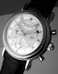
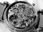
We‘ll leave you with a selection of pictures showing the completed movement in the case. Maybe you can imagine the feelings Lord Arran experienced when he had the chance to handle, hear and feel this masterpiece, after 14 years of waiting, fully completed for the first time!
After all these examples of excellent watch making art, please feel invited to meet Mr. Paul Gerber himself in an interview conducted directly after the accomplishment of the Ultra Complication!

The Introduction
The History
The Challenges
The complicated Complications
The Interview with Paul Gerber